Welcome to flame-gui's official user documentation! Use the quick index below to help find the things that may interest you.
Index
Getting Started
- Preparing a .lat and data file
- Inserting, editing, and removing model elements
- Graphing elements
- Configuring initial beam state
- Optimizing model
- Viewing model element phase space
General
- Canvas
- Canvas Toolbar
- Element View
- Element Configuration Window
- Optimization Window
- Initial Beam State Window
- Parameter Tree
- Phase Space Window
- Select Element Window
Documentation
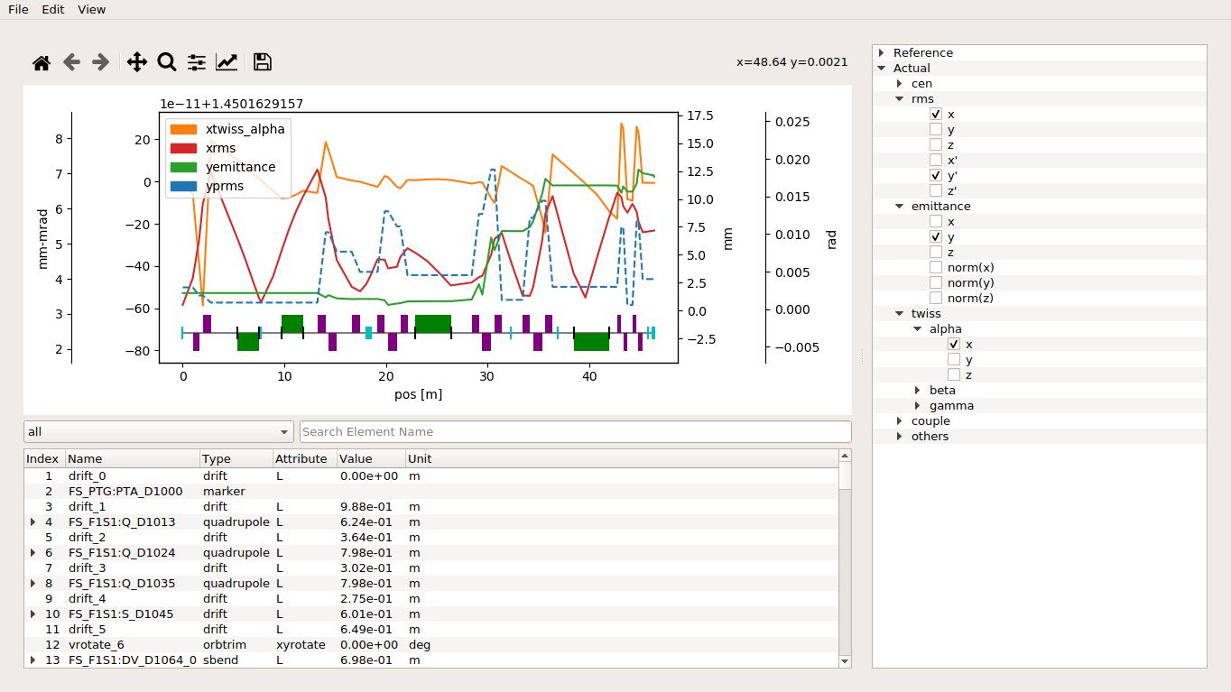
Canvas
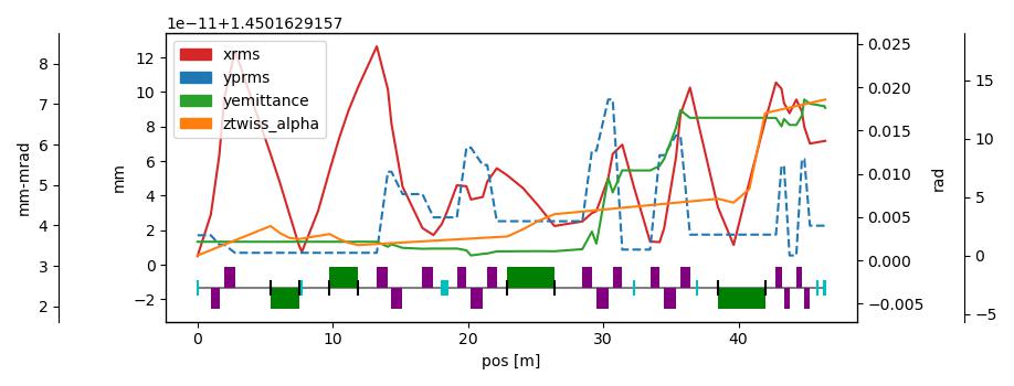
Displays the graph of the figure model.
How To Use
- Click & drag the legend to move it
- Add/Remove lines using the Parameter Tree
- Advanced control using the Canvas Toolbar
Default Colors

#d62728
#1f77b4
#2ca02c
#ff7f0e
Canvas Toolbar
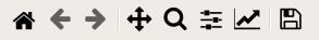
Advanced controls/commands for the Canvas.
Actions
Home– Reset to original viewBack– Back to previous viewForward– Forward to next viewPan– Pan throughout plotZoom– Zoom into plotConfigure plot– Manually configure borders/spacingsSelect Line Color– Manually change the color of a lineSave– Save a screenshot of the canvas
Color Dialog
Accessed from the
Select Line Coloraction within the Canvas Toolbar
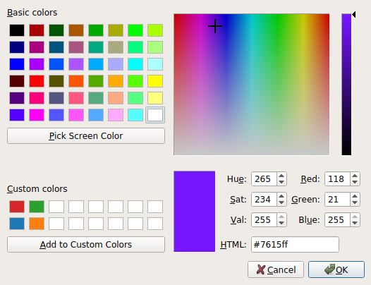
Helps you select a line color for the Canvas.
Element View
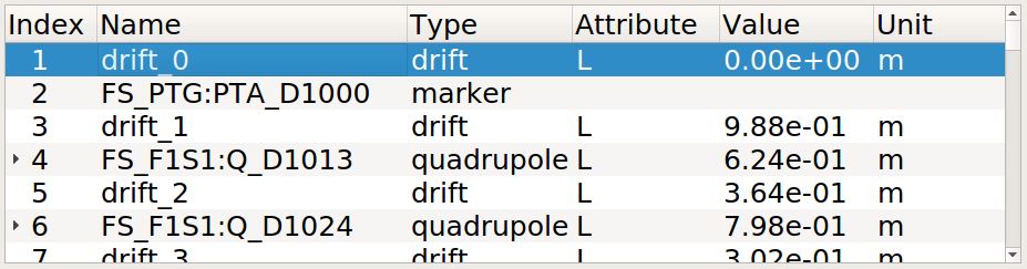
Expanding Elements
By pressing the ▶ button found within the index column, the element belonging to that index will be expand – bringing into the rest of its attributes into view.
Insert, Edit, and Remove Elements
By right-clicking the Element View, you will be presented with three options:
- Insert Element
- Edit Selected Element
Remove Element
Element Config Window
Accessed by right-clicking the Element View.
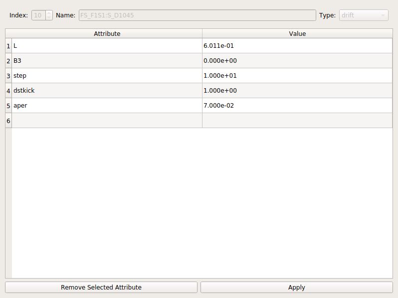
Used for inserting new and editing current elements.
Inserting Elements
After selecting Insert Element from Element View’s right-click menu, you will be find an element’s blank template. The element that you create here will be inserted at your selected index. Choose from each element type and required attributes and default values (such as the phi’s value) will be filled automatically.
Editing Elements
After choosing Edit Selected Element from Element View’s right-click menu, the element will be opened – making its attributes and their associated values available for edit. Note: element index, name, and type are unavailable for change.
Initial Beam State Window
Accessed from
Editon the menubar.
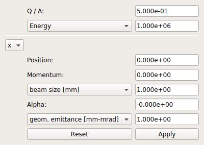
Set values for the initial beam state using this window.
How To Use
- Set any values
- Restore previous values using
Reset Apply
Optimization Window
Accessed from
Editon the menubar.
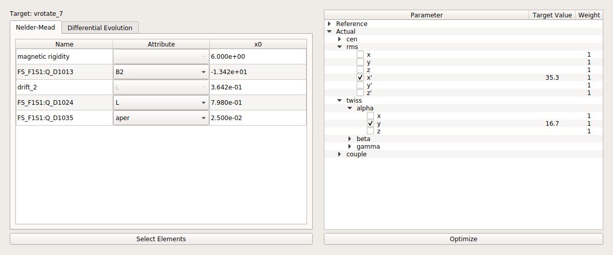
Optimize the model using selected knobs and target location.
Optimization Methods
How To Use
- Select Elements
- Set
x0values - Set
Target ValueandWeight(in relation to other parameters) Optimize
Parameter Tree
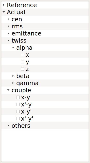
Used for selecting which parameters to graph (limited to four). After startup, the Parameter Tree will be completely collapsed.
How To Use
- To expand a category: use the
▶button - To collapse a category: use the
▼button - To select a parameter to graph: use the
☐button - To remove a parameter from the graph: use the
☑button
Phase Space Window
Accessed from
Viewon the menubar.
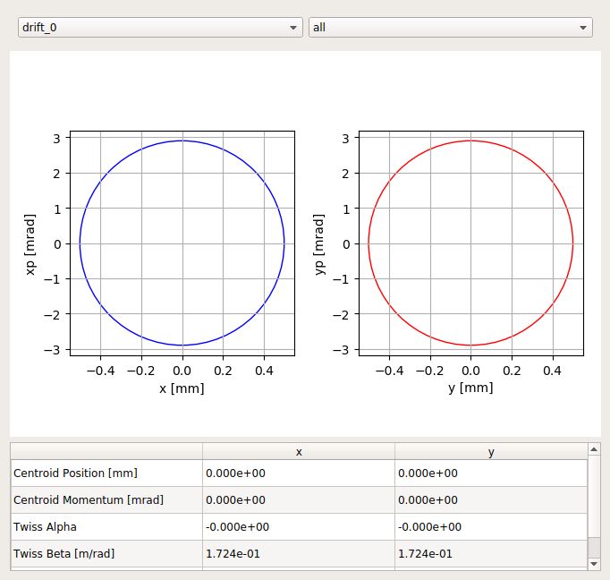
View the phase space plot for an element.
How To Use
- To select an element: use the box in the top-left
- To filter the selectable elements: use the box in the top-right
Select Element Window
Accessed from the Optimization Window
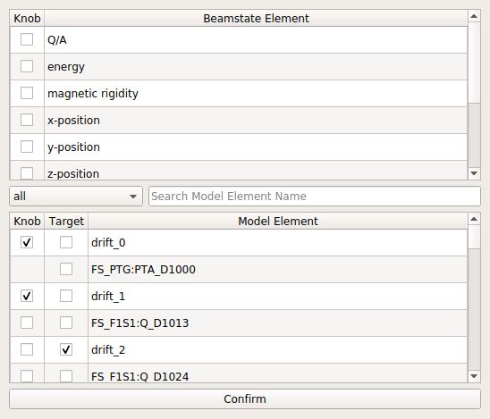
Choose the knobs and target location for optimization.
How To Use
- Filter elements by type or name (optional)
- Choose from beamstate/model elements any number of knobs and a target. This target must be at or beyond all knobs, otherwise your selection will be rejected and a pop-up will inform you of your error.
Confirm